
Database Diagramming on Steroids
SQL Server 2000 (and also SQL Server 7) has a good database-diagramming tool for displaying foreign-key relationships between tables. Some third-party tools carry this concept further and show dependencies between objects other than tables. For example, some tools can provide diagrams showing the dependencies between code objects such as stored procedures and tables. Being able to see the relationships between code and tables greatly facilitates impact analysis when considering changes to existing systems.
It is possible to generate full-dependency diagrams in SQL Server 2000 by resorting to a few tricks. By focusing on what the database-diagramming tool can do, rather than what it can’t do, and properly abstracting the problem, you can generate the desired diagram.
To understand the enhanced diagram technique, a review of the existing diagramming capabilities is in order. Selecting the Products table in the Northwind database produces the following diagram:
As the diagram clearly reveals, making a change to the Products table could impact the Order Details, Categories, and Suppliers tables. Helpful as that knowledge is, it is incomplete because there are other objects that have dependencies on the Products table.
The actual complexity of all dependencies on the Products table is much greater. The next diagram shows just a portion of these dependencies:
Click on this link to download the complete diagram of all Products table dependencies.
The full dependency diagram was created using the existing SQL Server 2000 diagramming feature. By downloading the script file from here, you can run a simple script to create new database objects just for generating enhanced database diagrams.
Abstracting the Diagramming Problem
Since the SQL Server diagramming tool can only draw parent-child foreign-key relationships, the problem must be adapted to fit this limited capability. For example, to draw the dependency that the CustOrderHist stored procedure has on the Products table, two new tables are created. They are called PROC CustOrderHist and TABL Products. By defining a foreign key in PROC CustOrderHist that refers back to TABL Products, the dependency between the actual objects CustOrderHist and Products can be drawn as a foreign key relationship between the two new tables PROC CustOrderHist and TABL Products.
In early tests of the modified database diagramming procedure, it was decided that cluttering the database with tables created just for drawing diagrams made things a bit messy. To keep the clutter down, a second database was created. The Northwind Diagram database contains the tables needed to fully diagram the Northwind database. One table in Northwind Diagram exists for every user table, function, stored procedure, and view in the Northwind database. Every foreign-key relationship and object dependency in Northwind is modeled as a foreign-key relationship in Northwind Diagram.
The script file queries the system metadata tables to generate DDL statements to create the tables and foreign-key relationships in the Northwind Diagram database. Tables are created by executing DDL statements such as this one:
create table [PROC CustOrderHist] (pk int primary key, fk int)
Every table name in the Northwind Diagram database has a prefix indicating what type of object it really is in the Northwind database. Notice that each table contains two columns, one for a primary key and one for a foreign key. Not every table needs a foreign column, but generically speaking, any given table might need a foreign-key column. When generating the DDL to create the tables, it is important to filter out objects that are not of interest. System views and SourceSafe stored procedures are excluded from the DDL script.
Once all of the new tables are created in Northwind Diagram, the next step is to create the foreign-key relationships. This requires DDL statements such as this one:
alter table [PROC CustOrderHist] add constraint fk_P_CustOrderHist_U_Customers
foreign key (fk) references [TABL Customers] (pk)
When generating the foreign-key DDL statements, it is also necessary to filter out self-dependencies.
You must generate one more set of DDL statements: The foreign-key DDL statements to model the actual foreign-key relationships in the original Northwind database. The statements look like this:
alter table [TABL Orders] add constraint fk_U_Orders_U_Customers foreign key (fk)
references [TABL Customers] (pk)
How the DDL Statements Are Generated
Examine the following T-SQL:
select
'create table ['
+ CASE rtrim(type)  -- rtrim is used because type is char(2)
      WHEN 'FN' THEN 'FUNS'  -- scalar FuNction
      WHEN 'IF' THEN 'FUNI'  -- Inline table Function
      WHEN 'P'  THEN 'PROC'  -- stored Procedure
      WHEN 'RF' THEN 'REPR'  -- Replication Filter stored procedure
      WHEN 'TF' THEN 'FUNT'  -- Table Function
      WHEN 'TR' THEN 'TRIG'  -- TRigger
      WHEN 'U'  THEN 'TABL'  -- User table
      WHEN 'V'  THEN 'VIEW'  -- View
      WHEN 'X'  THEN 'XPRC'  -- eXtended stored procedure
  END
+ ' ' + name + '] (pk int primary key, fk int)'
from sysobjects
In the previous example, a CASE statement was used to translate the object’s type into a four-character abbreviation indicating the object’s type in the original database.
The object’s type is constrained in the WHERE clause, limiting the results (the generated DDL) to only those object types of interest:
where rtrim(type) in ('FN','IF','P','RF','TF','TR','U','V','X')
With a little tweaking, the script even generated database diagram DDL for a Sybase database. The corresponding Sybase metadata tables were DTS imported into SQL Server, and the script file was modified to point to the copies of the Sybase metadata tables.
Running the Script
Before running the script, it’s a good idea to create a new, empty database. If you want to diagram, for example, Northwind, create a new database named Northwind Diagram. Just accept the defaults when creating the new database because the diagramming database won’t be large.
- Open a query window connected to the database you want to diagram. Set the results pane to display the Results in Text.
- Load the script file into the query window and execute it.
- Select all of the output in the results pane and paste it into a new query window. If you are creating the database diagrams in a new database such as Northwind Diagram, you must associate the query window with that database.
- Execute the DDL.
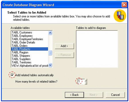
- Go the database-diagramming database and make your diagrams.
- Be sure to check the Add related tables automatically checkbox before making your selection. You may also want to adjust the number of levels of related tables.
- Select the objects of interest, click the Add > button, and then click the Next > button to create your diagram.
Conclusion
As you have seen, SQL Server 2000 can be adapted to generate database diagrams showing much more detail than you ever thought possible.
--
John Paul Cook is a database and systems architect in Houston, Texas. His primary focus is helping large enterprise customers succeed with regulatory compliance, SQL Server, C#, Oracle, and the .NET framework.
Contributors : John Paul Cook
Last modified 2006-01-06 10:44 AM