
IMS Structures and Functions
Part 2 in a series (Part 1 | Part 3)
This article discusses IMS database organization, access methods, secondary indexes, and logical relationships. It covers the following topics:
Control Blocks
When you create an IMS database, you tell IMS what the physical structure of the database will be-the segment names, segment lengths, the fields that each segment will contain, the segment's position in the hierarchy, and so on. You also tell IMS what segments can be accessed, whether they can be updated, deleted, or new ones inserted, and other access control specifications. You do this through a series of specifications that will be contained in control blocks, also called DL/I control blocks, because the DL/I command language is used perform the data manipulation functions. Control blocks do just what the name implies-they control the way in which IMS will structure and access the data stored in the database.
The data structure and control specifications you write will be contained in three major control blocks:
- DBD, which describes the database organization and access methods
- PSB, which describes an application program's view and use of the database
- ACB, which combines information from the DBD and PSB
Database Description
A database description (DBD) is a series of macro statements that define the type of database, all segments and fields, and any logical relationships or indexing. DBD macro statements are submitted to the DBDGEN utility, which generates a DBD control block and stores it in the IMS.DBDLIB library for use when an application program accesses the database.
Figure 2-1 shows a sample DBD for an HDAM database. When the DBD is assembled and link-edited, a load module is created and stored in an IMS DBDLIB library. In the DBDGEN process, each segment is assigned a segment code, a one-byte value in ascending sequence, that is used to identify the segment in physical storage.
In the DBD statement, an IMS access method and a system access method are specified (HDAM, OSAM in this example). The roles of the two access methods are discussed in greater detail in "Access Methods."
Fields within each segment can be defined as key fields or non-key search fields for use by application programs in retrieving segments. A key field is used for searching and sequencing. Each segment occurrence will be placed in a database record according to the sequence of the key fields. In Figure 2-1, the statement for field COLLID (college ID) is defined as a sequence field (SEQ) and as unique (U). Only fields that will be used in SSAs or that are key fields must be defined in the DBD.
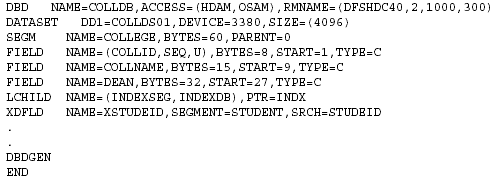
Figure 2-1: DBD for an HDAM database with secondary index.
The DBD contains the following statements:
| DATASET | Defines the DDname and block size of a data set. One DATASET statement is required for each data set group. |
| SEGM | Defines a segment type, its position in the hierarchy, its physical characteristics, and its relationship to other segments. Up to 15 hierarchic levels can be defined. The maximum number of segment types for a single database is 255. |
| FIELD | Defines a field within a segment. The maximum number of fields per segment is 255. The maximum number of fields per database is 1,000. |
| LCHILD | Defines a secondary index or logical relationship between two segments. It also is used to define the relationship between a HIDAM index and the root segment of the database. |
| XDFLD | Used only when a secondary index exists. It is associated with the target segment and specifies the name of the indexed field, the name of the source segment, and the field to be used to create the secondary index. See "The Role of Secondary Indexes" for more information. |
| DBDGEN | Indicates the end of statements defining the DBD. |
| END | Indicates to the assembler that there are no more statements. |
DBD Names the database being described and specifies its organization.
Program Specification Block
The program specification block (PSB) is a series of macro statements that describe the data access characteristics of an application program. Among other things, the PSB specifies:
- all databases that the application program will access
- which segments in the database that the application program is sensitive to
- how the application program can use the segments (inquiry or update)
A PSB consists of one or more program communication blocks (PCBs). The PCB specifies the segments to which the application program can have access and the processing authorization for each segment. You define a PCB for each database (or each view of the database) accessed by the application program. In the application program host code, you specify the PSB for that application.
For each PCB, you must code a corresponding block in the application program's linkage section. These data communication I/O areas are used for communication between IMS and the application. (There are actually two types of PCBs, a database PCB and a data communications PCB.)
PCBs contain SENSEG (sensitive segment) and SENFLD (sensitive field) statements. These statements allow you to specify which segments and fields the application program will "see." If you define a segment as sensitive, it will be accessible to the application. If you do not, it will be ignored by the application program. This gives you great flexibility in creating the views that application programs will have of your database.
The PSB macros are used as input to the PSBGEN utility, a macro assembler that generates a PSB control block. The PSB control block is stored in the IMS.PSBLIB library for use during database processing. There can be many PSBs for one DBD.
Figure 2-2 shows the structure of PSB generation input.
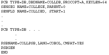
Figure 2-2: Sample PSBGEN generation input.
The PSB statements include the following:
| PCB | Defines the database to be accessed by the application program. The statement also defines the type of operations allowed by the application program. Each database requires a separate PCB statement. PSB generation allows for up to 255 database PCBs (less the number of alternate PCBs defined). |
| SENSEG | Defines the segment types to which the application program will be sensitive. A separate SENSEG statement is required for each segment type. If a segment is defined as sensitive, all the segments in the path from the root to that segment must also be defined as sensitive. Specific segments in the path can be exempted from sensitivity by coding PROCOPT=K in the SENSEG statement. |
| SENFLD | Defines the fields in a segment type to which the application program is sensitive. Can be used only in association with field-level sensitivity. The SENFLD statement must follow the SENSEG statement to which it is related. |
| PROCOPT | Defines the type of access to a database or segment. PROCOPTs can be used on the PCB or SENSEG statements. Primary PROCOPT codes are as follows: |
| G read only | |
| R replace, includes G | |
| I insert | |
| D delete, includes G | |
| A get and update, includes G, R, I, D | |
|
K used on SENSEG statement; program will have key-only sensitivity to this segment |
|
| L load database | |
| Secondary PROCOPT codes are as follows: | |
| E exclusive use of hierarchy or segments | |
| O get only, does not lock data when in use | |
| P must be used if program will issue path call using the D command code | |
|
S sequential (LS is required to load HISAM and HIDAM databases; GS gets in ascending sequence) |
Application Control Block
Application control blocks (ACBs) are created by merging information from PSBs and DBDs. For online applications, ACBs must be prebuilt using the ACB maintenance utility. For batch applications, ACBs can be built dynamically using DBDLIB and PSBLIB as input (PARM=DL/I) or the prebuilt ACB from ACBLIB can be used (PARM=DBB). The ACBGEN process is shown in Figure 2-3.
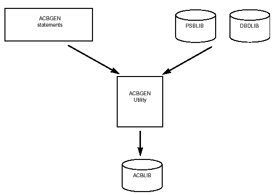
Figure 2-3: ACB generation.
Prebuilt ACBs require less time to schedule an application program and use less storage. The ACB maintenance utility also provides some error-checking capability.
ACBs can be built for all PSBs, for particular PSBs, or for all PSBs that reference a particular DBD. Prebuilt ACBs are stored in the IMS.ACBLIB library. During ACB generation, the ACB maintenance utility must have exclusive control of the IMS.ACBLIB. Because of this, the utility must be executed using an IMS.ACBLIB that is not currently allocated to an active IMS system. You can execute the ACB maintenance utility against an inactive copy of ACBLIB, then use the IMS Online Change function to make the new members available to an active IMS online system.
Access Methods
IMS accesses data after it has been retrieved from DASD and places it in a buffer pool in memory. The task of retrieving the data from DASD is performed by one of several system access methods. These should not be confused with IMS access methods such as HSAM, HISAM, HDAM, HIDAM, and so on. IMS access methods are actually types of database organizations. In IMS terminology, however, databases often are referred to by their IMS access method. An IMS database definition must always specify an IMS access method and a system access method. In some cases, you can choose the type of system access method you want to use. In other cases, the system access method is dictated by the IMS access method. HISAM, for instance, uses only VSAM.
Both the system and IMS access methods are used for IMS database retrieval and update. Application programs specify the data to retrieve and make a DL/I call to the system access method. The system access method returns a block of data to IMS. The IMS access method then locates the data within the block and passes it to the application program. The IMS database types and their access methods are shown in Table 2-1.
Table 2-1: IMS database and system access types.
VSAM
In the discussion on HISAM and HIDAM databases later in this chapter, you will find reference to VSAM, particularly in association with VSAM key-sequenced data sets (KSDSs) and entry-sequenced data sets (ESDSs), because of the way in which certain databases use these data sets. Before discussing the various IMS access methods, it is helpful to have an understanding of VSAM's role in the storage and retrieval of data. VSAM performs the physical I/O of data for IMS. It retrieves the data from DASD and places it in the main storage buffer pool for use by IMS. When processing has been completed, VSAM returns the data to DASD, where it is stored until needed again. To perform these functions, VSAM uses its own set of data storage and retrieval structures.
A VSAM data set consists of a set of records. The records are grouped into control intervals (CIs), which in turn are grouped into larger groupings called control areas (CAs). The layout of a control interval is shown in Figure 2-4.
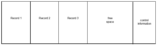
Figure 2-4: VSAM control interval layout.
A VSAM CI consists of records, free space, and control information. You can determine the size of a CI or let VSAM do it for you. When you define the size of a CI for a data set, all CIs in the data set will be the same size. When you define the CI, you also determine the percentage of free space to be designated. You will attempt to create enough free space to avoid CI splits while not using so much free space that you waste DASD. CI splits occur when there is no room to insert another record; consequently, VSAM moves half of the records from the CI where the record was to be inserted to a new CI. CI splits are a costly overhead, especially in high-activity systems. (You can correct CI splits by reorganizing the database.)
CIs are grouped inside a control area (CA). The goal is to have enough unused CIs to allow new data to be added without causing a CA split. CA splits are more processing-intensive than CI splits. On the other hand, you don't want to waste DASD by defining too many unused CIs. For information on calculating space requirements, refer to the IBM manuals IMS/ESA Administration Guide: Database Manager and IMS/ESA Administration Guide: System.
The control information portion of the CI contains two types of fields:
- The record definition field (RDF) contains information on the records stored in the CI, their length, and whether they are fixed or variable length.
- The control interval definition field (CIDF) contains information on the CI itself. It keeps track of the amount of free space available and where the free space is located relative to the beginning of the CI. CIs have only one CIDF but may have a variable number of RDFs, depending on whether the CI contains fixed-length or variable-length records or a combination of the two.
Sequence Sets and Indexes
For KSDSs, VSAM keeps track of all CAs and CIs through the use of two levels of indexing-the sequence set and the index set.
VSAM maintains a sequence set record for each CA in the data set. The sequence set record contains an entry for each CI in the CA. Each entry contains the key of the highest record in the CI and a pointer to the CI. The index contains an entry for each sequence set record. This gives the index an entry for each CA, since there is a sequence set for every CA. Each index entry contains the key of the highest record in its CA and a pointer to the sequence set record for that CA.
By following the values of record keys from index to sequence set to CA to CI, VSAM can locate any record in the data set. When VSAM reaches the CI, it can obtain record information from the CIDF and RDFs of the CI. The example in Figure 2-5 illustrates this concept.
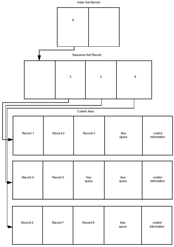
Figure 2-5: Structure of VSAM index set and sequence set records.
Key-Sequenced Data Sets
The data sets we have described so far have been key-sequenced data sets (KSDSs). You can see that the name derives from the way VSAM stores and retrieves records based on the record key.
VSAM can retrieve the records in a KSDS in a number of ways. The simplest and most obvious way is to read each record in the logical order (lowest key to highest key) in which they are stored. This is called sequential retrieval. Obviously, this method has limitations if you want only some of the records or if you want them in other than key sequence order.
VSAM can use the key sequence retrieval method to return only a portion of the records. This method is called keyed sequential retrieval or skip sequential retrieval. With this method, you specify the keys of the records you want retrieved, but they must be in ascending order. Another method, addressed sequential retrieval, locates the records to be retrieved by their RBA (relative byte address-the number of bytes from the beginning of the data set to the beginning of the record). You must supply the RBAs to VSAM. Addressed sequential retrieval can be used with KSDSs but is primarily designed for ESDSs.
VSAM can also retrieve KSDS records directly. You provide the record key, and VSAM uses the index set and sequence set to navigate its way to the correct CI and to the record you requested. With this method, you can retrieve records in any order.
VSAM can retrieve a record directly by its RBA. This method, addressed direct retrieval, like addressed sequential retrieval, is designed primarily for ESDSs.
Entry-Sequenced Data Sets
Entry-sequenced data sets (ESDSs) are stored in the order in which they are loaded, rather than by key sequence. With ESDSs, VSAM does not create an index and does not reserve free space. No index is needed because there are no record keys to track. Likewise, free space is not needed because the next record added to the data set is stored at the end of the existing set of records. If a record is too large to fit in the CI being loaded, VSAM creates a new CI and puts the record there. VSAM does not attempt to use space that may be left at the end of each CI.
ESDSs are retrieved only by RBA using either addressed sequential retrieval or addressed direct sequential retrieval. With addressed sequential retrieval, you give VSAM the RBA of the first record. It retrieves the succeeding records by computing their RBA based on the record length field of each record's RDF. With the addressed direct method, you must supply VSAM with the RBA of each record you want.
Because of their storage and retrieval mechanisms, ESDSs have certain limitations that make them less attractive for many applications. Although updating is relatively simple, adding and deleting records proves more difficult. With updating, you read the record, enter changes, and rewrite it, without changing the record length. To delete, you read the record and mark it for deletion, but VSAM does not physically delete the record or reclaim the unused space. To add a record, you must add it at the end of the data set.
QSAM
The queued sequential access method (QSAM) processes records sequentially from the beginning of the data set. QSAM groups logical records into physical blocks before writing them to storage and handles the blocking and deblocking of records for you. QSAM is typically used by application programs that retrieve or create a single member at a time within a partitioned data set (PDS). The characteristics of a member of a PDS-which is a collection of sequentially organized members-are the same as those of a sequential data set.
BSAM
The basic sequential access method (BSAM) allows you to read and write physical records only. It does not perform blocking or deblocking of records. With BSAM, you can begin processing a data set at any point
BDAM
The basic direct access method (BDAM) allows you to write or retrieve records directly by address, using the physical track, relative track, or relative record number.
OSAM
The overflow sequential access method (OSAM) was developed for use with DL/I databases. It combines many features of sequential access methods and of BDAM. To the operating system, an OSAM data set appears the same as a sequential data set. An OSAM data set can be read with BSAM or QSAM. OSAM allows direct access to records.
Database Organizations
The nine types of databases supported by IMS can be grouped by their IMS access method. Hierarchic sequentially accessed databases include
- HSAM
- SHSAM
- HISAM
- SHISAM
- GSAM
Hierarchic direct databases include
- HDAM
- HIDAM
Fast Path databases provide fast access with limited functionality
- DEDB
- MSDB
Hierarchic Sequential Databases
The earliest IMS database organization types were based on sequential storage and access of database segments. Hierarchic sequential databases share certain characteristics. Compared to hierarchic direct databases, which we will discuss later, hierarchic sequential databases are of simpler organization. The root and dependent segments of a record are related by physical adjacency. Access to dependent segments is always sequential. Deleted dependent segments are not physically removed but are marked as deleted. Hierarchic sequential databases can be stored on tape or DASD.
HSAM
In a hierarchic sequential access method (HSAM) database, the segments in each record are stored physically adjacent. Records are loaded sequentially with root segments in ascending key sequence. Dependent segments are stored in hierarchic sequence. The record format is fixed-length and unblocked. An HSAM database is updated by rewriting the entire database. Although HSAM databases can be stored on DASD or tape, HSAM is basically a tape-based format. Figure 2-6 shows an HSAM database record and segment format.
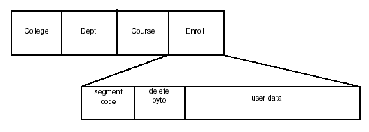
Figure 2-6: HSAM database segment structure.
IMS identifies HSAM segments by creating a two-byte prefix consisting of a segment code and a delete byte at the beginning of each segment. HSAM segments are accessed through two operating system access methods:
- basic sequential access method (BSAM)
- queued sequential access method (QSAM)
QSAM is always used as the access method when the system is processing online, but you can specify either method for batch processing through the PROCOPT parameter in the PCB.
Entry to an HSAM database is through GET UNIQUE (GU) or GET NEXT (GN) calls. The first call starts at the beginning of the database and searches sequentially through the records until it locates the requested segment. Subsequent calls use that position as the starting point for calls that process forward in the database.
HSAM databases are limited by the strictly sequential nature of the access method. DELETE (DLET) and REPLACE (REPL) calls are not allowed, and INSERT (ISRT) calls are allowed only during the database load. Field-level sensitivity is provided, but HSAM databases are limited in the number of IMS options they can use.
Because of the numerous limitations, HSAM databases see limited use and are reserved primarily for applications that require sequential processing only.
SHSAM
A simple HSAM (SHSAM) database contains only one type of segment-a fixed-length root segment. Because there is no need for a segment code and deletes are not allowed, there is no need for a prefix portion of a SHSAM database segment. Because they contain only user data, SHSAM databases can be accessed by BSAM and QSAM. The only DL/I calls used with SHSAM databases are the GET calls. Like HSAM, SHSAM database segments can be deleted or inserted only during a reload.
HISAM
The hierarchic indexed sequential access method (HISAM) database organization adds some badly needed capabilities not provided by HSAM. Like HSAM, HISAM databases store segments within each record in physically adjacent sequential order. Unlike HSAM, each HISAM record is indexed, allowing direct access to each record. This eliminates the need to read sequentially through each record until the desired record is found. As a result, random data access is considerably faster than with HSAM. HISAM databases also provide a method for sequential access when that is needed.
A HISAM database is stored in a combination of two data sets. The database index and all segments in a database record that fit into one logical record are stored in a primary data set that is a VSAM KSDS. Remaining segments are stored in the overflow data set, which is a VSAM ESDS. The index points to the CI containing the root segment, and the logical record in the KSDS points to the logical record in the ESDS, if necessary.
If segments remain to be loaded after the KSDS record and the ESDS record have been filled, IMS uses another ESDS record, stores the additional segments there, and links the second ESDS record with a pointer in the first record. You determine the record length for the KSDS and the ESDS when you create the DBD for the database.
If segments are deleted from the database, they are still physically present in the correct position within the hierarchy, but a delete byte is set to show that the record has been deleted. Although the segment is no longer visible to the application program, it remains physically present and the space it occupies is unavailable until the database is reorganized. The only exception to this is the deletion of a root segment where the logical record in the VSAM KSDS is physically deleted and the index entry is removed; any VSAM ESDS logical records in the overflow data set are not be deleted or updated in any way.
Inserting segments into a HISAM database often entails a significant amount of I/O activity. Because IMS must enforce the requirement for segments to be physically adjacent and in hierarchic order, it will move existing segments within the record or across records to make room for the insertion; however, any dependent segments are not flagged as deleted. To facilitate indexing, HISAM databases must be defined with a unique sequence field in each root segment. The sequence fields are used to construct the index.
HISAM databases are stored on DASD, and data access can be much faster than with HSAM databases. All DL/I calls can be used against a HISAM database. Additionally, HISAM databases are supported by a greater number of IMS and MVS options.
HISAM databases work well for data that requires direct access to records and sequential processing of segments within each record.
Figure 2-7 shows the database structure for HISAM. Notice that four ESDS records have been used in loading one logical record. The arrows represent pointers.
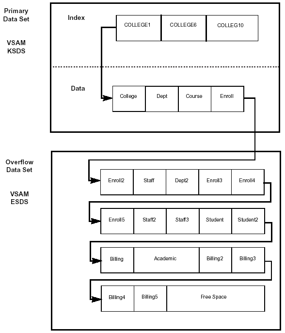
Figure 2-7: HISAM database structure.
HISAM Segment Structure
Figure 2-8 shows the HISAM segment structure.
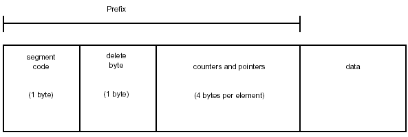
Figure 2-8: HISAM segment structure.
A HISAM segment contains the following fields:
| Segment Code | 1 byte. The segment code byte contains a one-byte unsigned binary number that is unique to the segment type within the database. The segments are numbered in hierarchic order, starting at 1 and ending with 255 (X'01' through X'FF'). |
| Delete Byte | 1 byte. The delete byte contains a set of flags. |
Counters and Pointers
The appearance of this area depends on the logical relationship status of the segment:
- If the segment is not a logical child or logical parent, this area is omitted.
- If the segment is a logical child, and if a direct pointer (see "Pointer Types") is specified (the logical parent must be in an HD database), the four-byte RBA of the logical parent will be present.
- If the segment is a logical parent and has a logical relationship that is unidirectional or bidirectional with physical pairing, a four-byte counter will exist.
If the segment is a logical parent and has one or more logical relationships that are bidirectional with virtual pairing, then for each relationship there is a four-byte RBA pointer to the first logical child segment (a logical child first pointer) and, optionally, a four-byte RBA pointer to the last logical child segment (a logical child last pointer), depending on whether you specified LCHILD=SNGL or LCHILD=DBLE in the DBD.
There is only one counter in a segment, but there can be multiple logical child first (LCF) and logical child last (LCL) pointers. The counter precedes the pointers. The pointers are in the order that the logical relationships are defined in the DBD, with a logical child first pointer before a logical child last pointer.
Figure 2-9 shows a segment with multiple logical child pointers.
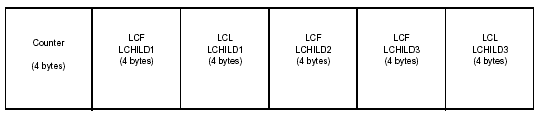
Figure 2-9: Multiple logical child pointers in a segment.
Data
The length of the data area (which is specified in the DBD) can be a fixed length or a variable length. For a logical child segment with symbolic keys (PARENT=PHYSICAL on the SEGM statement), the concatenated key of the logical parent will be at the start of the segment.
If the segment is variable length, the first two bytes of the data area are a hexadecimal number that represents the length of the data area, including the two-byte length field.
SHISAM
As is the case with SHSAM, a simple HISAM (SHISAM) database contains only a root segment, and its segment has no prefix portion. SHISAM databases can use only VSAM as their access method. The data must be stored in a KSDS. All DL/I calls can be used with SHISAM databases, and their segments can be accessed by DL/I calls and VSAM macros.
GSAM
Generalized sequential access method (GSAM) databases are designed to be compatible with MVS data sets. They are used primarily when converting from an existing MVS-based application to IMS because they allow access to both during the conversion process. To be compatible with MVS data sets, GSAM databases have no hierarchy, database records, segments, or keys. GSAM databases can be based on the VSAM or QSAM/BSAM MVS access methods. They can have fixed-length or variable-length records when used with VSAM or fixed-length, variable-length, or undefined-length records when used with QSAM/BSAM.
Hierarchic Direct Databases
Hierarchic direct access method (HDAM) and hierarchic indexed direct access method (HIDAM) databases are referred to collectively as HD databases. The hierarchic direct databases were developed to overcome some of the deficiencies of sequential access databases. HD databases share these characteristics:
- Pointers are used to relate segments.
- Deleted segments are physically removed.
- VSAM ESDS or OSAM data sets are used for storage.
- HD databases are stored on DASD.
- HD databases are of a more complex organization than sequentially organized databases.
The following sections discuss HDAM, PHDAM, HIDAM and PHIDAM database organizations. Because pointers play such an integral role in direct access databases, they are referenced frequently in the text. Pointers are four-byte address values that give the offset from the beginning of the data set of the segment being addressed. They tie the segments together without the need for segments to be physically adjacent. Segments can be inserted or deleted without the need to move other segments. There are different types of pointers. Pointers are discussed in greater detail in "Pointer Types" below.
HDAM
HDAM databases are typically used when you need fast access to the root segment of the database record, usually by direct access. In a hierarchic direct access method (HDAM) database, the root segments of records are randomized to a storage location by an algorithm that converts a root's key into a storage location. No index or sequential ordering of records or segments is involved. The randomizing module reads the root's key and, through an arithmetic technique, determines the storage address of the root segment. The storage location to which the roots are randomized are called anchor points or root anchor points (RAPs). The randomizing algorithm usually attempts to achieve a random distribution of records across the data set. Theoretically, randomizing the location of records minimizes the number of accesses required to retrieve a root segment.
The randomizing technique results in extremely fast retrieval of data, but it usually does not provide for sequential retrieval of records. This can be achieved in HDAM databases through the use of secondary indexes or by using a physical-key-sequencing randomizer module.
The advantage of HDAM is that it does not require reading an index to access the database. The randomizing module provides fast access to root segments and to the paths of dependent segments. It uses only the paths of the hierarchy needed to reach the segment being accessed, further increasing access speed. The disadvantage is that you cannot process HDAM databases in key sequence unless the randomizing module stores root segments in physical key sequence.
An HDAM database consists of one data set split into two parts: the root addressable area (RAA) and the overflow area. The data set can be a VSAM ESDS or an OSAM data set. You specify which access method to use in the DBD ACCESS parameter.
In designing an HDAM database, you decide the size of the RAA and the number of CIs (or blocks, if you are using OSAM) that it will be broken down into. Within a CI or block, you define the number of Raps The randomizer uses these parameters in establishing a storage location for the root segment of the record. The CI does not contain just RAAs and Raps It also is used for storage of the record's dependent segments. Each CI begins with a free space element anchor point (FSEAP) area. The FSEAP is used to locate free or unused space in the block. When IMS inserts new segments in the block, it updates the FSEAP.
Figure 2-10 shows how a record appears in an HDAM database.
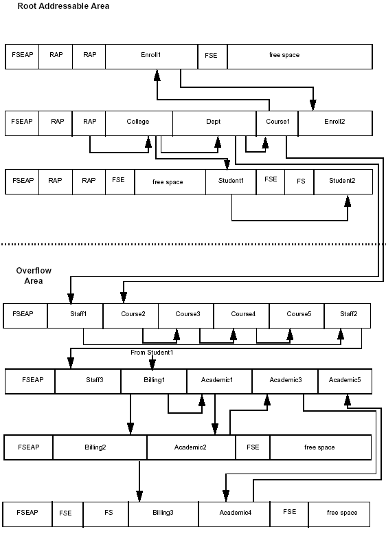
Figure 2-10: HDAM database structure.
Three CIs are in the RAA, and four CIs are in the overflow area. Together, they make up the data set. Each CI in the RAA contains two Raps In the example, the College record randomized to the second RAP in the second CI in the data set. The RAP does not contain the root segment. It contains a four-byte pointer that contains the address of the root segment.
After an initial load, segments within a database record are very likely to be grouped together in blocks/CIs in hierarchic order. After update activity, this may not be the case.
To insert a root segment, IMS invokes the HDAM randomizer that has been specified in the DBD. This determines the RAP from which the root must be chained.
When a segment has been inserted in an HDAM database, the segment is never moved so that all the direct address pointers are preserved. The example assumes physical child first pointers and twin forward pointers are specified for all segment types. If, as in the case under consideration, there are more segments in the database record at initial load than the BYTES parameter in the DBD will allow to be inserted in the RAA, all other segments will be inserted into overflow. This is also true for multiple inserts of segments within the same database record during the same synchronization point. If the database were to use multiple data set groups, each secondary data set group would have the format of the overflow part of an HDAM database.
If segments are deleted from the database segment, they are physically deleted from the data set and the space is designated as free space.
Bit Maps
In HD databases, bit maps are used to keep track of free space. A bit map is a string of bits that indicate whether enough space is available in a CI or OSAM block to contain an occurrence of the longest segment defined for the data set. In a VSAM ESDS, the bit map is located in the second CI of the data set. (The first CI is reserved.) In OSAM, bit maps are put in the first block of the first extent of the data set.
As you read the bits in a bit map from left to right, they reflect the status of the corresponding CI or block following the bit map. The bits are set as follows:
- 0 if not enough space exists in the CI or block
- 1 if there is adequate space for the longest segment specified for the data set.
For example, if the first bit is set to 1, the first CI or block following the block containing the bit map will have space available. If the third bit in the bit map is set to 0, the third CI or block following that containing the bit map will not have sufficient space available, and so on. As data is added and new CIs are created, the number of CIs may reach the size limit of the bit map. If so, another bit map is created and the process repeated for CIs that are added subsequently.
Free Space Element Anchor Point
Another specialized field, the free space element anchor point (FSEAP), is used in determining the availability of free space within a CI or block. As shown in Figure 2-10, the FSEAP is located at the beginning of each CI or OSAM block in a data set. An FSEAP is made up of two 2-byte fields. The first field contains the offset, in bytes, to the first free space element (FSE) in the block. An FSE is associated with each area of free space within the block or CI. The FSEs in a CI are chained together using pointers. The second field in the FSEAP tells whether this block or CI contains a bit map.
Free Space Element
In addition to an FSEAP, each OSAM block or VSAM CI contains free space elements (FSEs) that provide information about the free space available in the block. The FSE makes up the first eight bytes of each area of free space. It consists of the following fields:
- Free space chain pointer (CP). This 2-byte field gives the offset in bytes to the beginning of the next FSE in the block or CI. If it is the last FSE in the block, it is set to zero.
- Available length field (AL). This 2-byte field gives the length of the free space area, including the length of the FSE.
- Task ID field (ID). This 4-byte field contains the task ID of the program that freed the space. This field is used to allow a program to reuse the same space during a specified period without contending with other programs for the space.
PHDAM
PHDAM databases are partitioned HDAM databases. Each PHDAM database is divided into a maximum of 1001 partitions which can be treated as separate databases. A PHDAM database is also referred to as a High Availability Large Database (HALDB).
HIDAM
Unlike HDAM, HIDAM databases use an index to locate root segments. HIDAM databases are typically used when you would like to access database records randomly and sequentially and also access segments randomly within a record. The index and the database are stored in separate data sets. The index is stored as a single VSAM KSDS. The database is stored as a VSAM ESDS or OSAM data set. The index stores the value of the key of each root segment, with a four-byte pointer that contains the address of the root segment.
The root segment locations in the index are stored in sequential order, allowing HIDAM databases to be processed directly or sequentially. A disadvantage of HIDAM databases is that the additional step required to scan an index makes access slower than with HDAM databases.
When you access a record by root key, IMS searches for the key in the index and uses the pointer to go directly to the record. If the PTR =TB or PTR=HB (twin backward pointer or hierarchic backward pointer) parameter is defined for the root, the root segments are chained together in ascending order. Sequential processing is done by following this pointer chain. In HIDAM, Raps are generated only if you specify the PTR=T or PTR=H (twin pointer or hierarchic pointer) parameter for the root. When either of these pointer parameters is defined, IMS puts one RAP at the beginning of the CI or block. Root segments within the CI or block are chained by pointers from the most recently inserted back to the first root on the RAP. The result is that the pointers from one root to the next cannot be used to process roots sequentially. Sequential processing must be performed by using key values, which requires the use of the index and increases access time. For this reason, you should specify PTR=TB or PTR=HB for root segments in HIDAM databases.
Figure 2-11 shows how the database record exists in a HIDAM database.
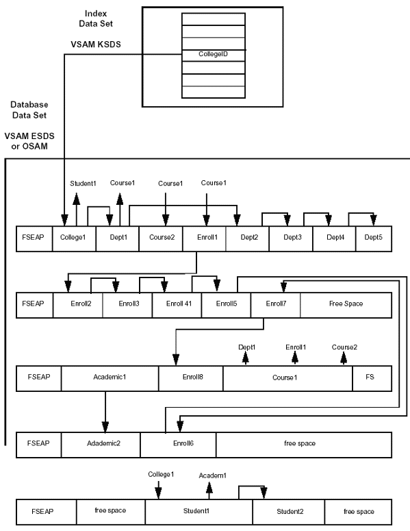
Figure 2-11: HIDAM database structure.
After an initial load, segments within a database record are stored physically in blocks/CIs in hierarchic order. After update activity, this may not be the case.
When a segment has been inserted in a HIDAM database, the segment is never moved to preserve all the direct address pointers. The example assumes that physical child first pointers and twin forward pointers are specified for all segment types.
If segments are deleted from the database segment, they are physically deleted from the data set, and the space is designated as free space. If the database has multiple data set groups, each secondary data set group has the format of the main part of the HIDAM database.
PHIDAM
PHIDAM databases are partitioned HIDAM databases. Each PHIDAM database is divided into a maximum of 1001 partitions which can be treated as separate databases. A PHIDAM database is also referred to as a High Availability Large Database (HALDB).
HDAM/HIDAM Segment Structure
Figure 2-12 shows the HDAM/HIDAM segment structure.
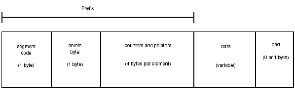
Figure 2-12: HDAM/HIDAM segment structure.
An HDAM/HIDAM segment contains the following fields:
| Segment Code | 1 byte. The segment code byte contains a one-byte unsigned binary number that is unique to the segment type within the database. The segments are numbered in hierarchic order, starting at 1 and ending with 255 (X'01' through X'FF'). |
| Delete Byte | 1 byte. The delete byte contains a set of flags. |
Counters and Pointers
The following four-byte fields can be in this area and, if present, will occur in the following order:
Counter
If the segment has a logical relationship that is unidirectional or bidirectional with physical pairing, a four-byte counter will exist.
Hierarchic or Physical Twin Pointers
A hierarchic forward pointer or a twin forward pointer must be present in the segment prefix, unless PTR=NOTWIN was specified in the SEGM statement. Hierarchic backward pointers or twin backward pointers can also be present (PTR=HB or PTR=TB on SEGM statement).
Physical Parent Pointer
This pointer will be present if the segment is a logical child or has a logical child below it in the hierarchy. It will also be generated if the segment is a logical parent or has a logical parent below it in the hierarchy.
It is also present in any segments that are target segments for a secondary index or that lie on the hierarchical paths between the root segment and any target segments.
Logical Twin Pointers
A logical twin forward pointer and a logical twin backward pointer exist only in a logical child segment with a bidirectional logical relationship that is virtually paired. A logical twin backward pointer will be present if LTWINBWD is specified on the SEGM statement of the logical child segment.
Logical Parent Pointer
A logical child segment can have a direct pointer to its logical parent (PHYSICAL specified on SEGM statement) if the logical parent is in an HD database.
Logical Child Pointers
If the segment is a logical parent and has one or more logical relationships that are bidirectional with virtual pairing, for each relationship there is a four-byte RBA pointer to the first logical child segment (a logical child first pointer). There can also be a four-byte RBA pointer to the last logical child segment (a logical child last pointer), depending on whether you specified LCHILD=SNGL or LCHILD=DBLE in the DBD. The pointers are in the order that the logical relationships are defined in the DBD, with a logical child first pointer before a logical child last pointer.
Physical Child Pointers
If physical pointers rather than hierarchical pointers have been chosen for the segment, there is a four-byte RBA pointer to the first physical child segment (a physical child first pointer). There can also be a four-byte RBA pointer to the last physical child segment (a physical child last pointer). The pointers are in the order that the physical children are defined in the DBD, with a physical child first pointer before a physical child last pointer.
Figure 2-13 shows a logical parent with unidirectional relationships, two bidirectional virtually paired relationships (the second with backward pointers), and three physical segments (the second with backward pointers).
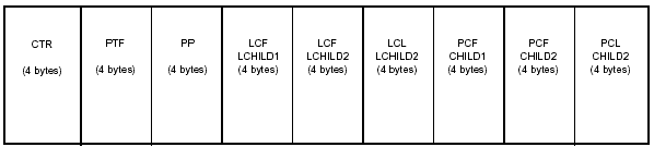
Figure 2-13: Sample counter and pointers in a typical HD-type segment.
| Data | The data area can be a fixed length that is specified in the DBD or variable length (described in "Variable-Length Segment Structure"). For a logical child segment with symbolic keys (PARENT=PHYSICAL on the SEGM statement), the concatenated key of the logical parent will be at the start of the segment. |
| Data Pad | If the segment length is an odd number of bytes, a one-byte pad will be appended to the segment to ensure that all segments start on half-word boundaries. |
Variable-Length Segment Structure
Figure 2-14 depicts a variable-length segment (VLS) that can exist in HISAM, HDAM, and HIDAM databases.
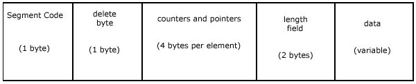
Figure 2-14: Variable length segment structure.
Variable-length segments contain the following fields:
| Segment Code | See the definition for the appropriate database organization. |
| Delete Byte | See the definition for the appropriate database organization. |
| Counters and Pointers | See the definition for the appropriate database organization. |
| Length Field | 2 bytes. Signed binary number that specifies the length of the data portion of the segment, including the length field itself. |
| Data | See the definition for the appropriate database organization. If a variable-length segment in a HISAM database is replaced and is longer than it was before, IMS moves the following segments to make room for the new segment. IMS does not move HDAM and HIDAM database segments once they have been inserted. Instead, it splits the segment, leaving the prefix part in the original location and inserting the data part in another location. The two parts are connected by a VLS pointer. |
You can make a segment variable in length in one of two ways:
- by specifically defining it to be variable in length by using the SIZE operand in the SEGM macro of the DBD
- by implicitly defining it to be variable length by using the COMPRTN (compression routine) operand in the SEGM macro of the DBD
Use of a compression routine always makes the segment variable length in the data, but may be presented to the user through a DL/I call as fixed length. How the user sees the segment data is determined by the SIZE parameter in the DBD.
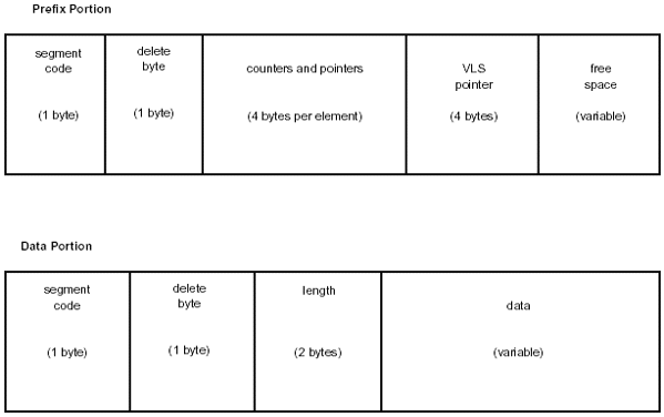
Figure 2-15: Split variable length segment structure.
Prefix Portion
The prefix portion contains the following fields:
| Segment Code | See the definition for the appropriate database organization. |
| Delete Byte | See the definition for the appropriate database organization. BIT 4 is on, indicating that the prefix and data are separated. Typically this is X'08'. |
| Counters and Pointers | See the definition for the appropriate database organization. |
| VLS Pointer | 4 bytes. RBA of the data part of the variable length segment. |
| Free Space | Normal IMS free space (see "Free Space Element"). |
Data Portion
The data portion contains the following fields:
| Segment Code | See the definition for the appropriate database organization. |
| Delete Byte | This will always be X'FF'. |
| Length Field | 2 bytes. Signed binary number that specifies the length of the data portion of the segment, including the length field. |
| Data | See the definition for the appropriate database organization. |
Pointer Types
Pointers play an important role in accessing data stored in hierarchic direct access and indexed databases. An understanding of the various types of pointers and how they are used is important in understanding how database segments are accessed.
In HD databases, the records are kept in hierarchical sequence through the use of pointers-four-byte fields that contain the address of another segment. The prefix in every HD segment contains one or more pointers, and each pointer contains the relative byte address (relative to the beginning of the database) of the segment to which it points.
There are a number of types of pointers, and they can be mixed within a database record to meet specific data access requirements.
Hierarchic Forward Pointers
Hierarchic forward (HF) pointers point to the next segment in the hierarchy. Segments are located by following the HF pointers to the desired segment. This is essentially the same as using a sequentially accessed database. As with a sequential database, when HF pointers are used, all the segments in the hierarchy must be searched until the requested segment is located. HF pointers are most suitable for databases where segments are typically processed in hierarchic sequence.
Figure 2-16 shows an example of hierarchic forward pointers.
Figure 2-16: Examples of Hierarchic Forward Pointers.
Hierarchic Forward and Hierarchic Backward Pointers
With hierarchic forward (HF) and hierarchic backward (HB) pointers, each segment points to the next segment and the previous segment in the hierarchy. Because HF and HB pointers are four bytes each, combining them requires eight bytes in each dependent segment. Root segments require 12 bytes, because the root points forward to the next root, backward to the previous root, and forward to the first dependent segment.
Physical Child First Pointers
With physical child first (PCF) pointers, each parent segment points to the first occurrence of each of its immediate child segment types. No pointers exist to connect occurrences of the same segment type under a parent, which means that the hierarchy is not completely connected. Physical twin (PT) pointers can be used to connect twin segments and complete the hierarchy.
Physical Child First and Physical Child Last Pointers
With physical child first (PCF) and physical child last (PCL) pointers, each parent segment in a record points to the first and last occurrence of its immediately dependent segment types. PCL pointers cannot be used alone; PCF pointers must be used with them.
PCL pointers are most often used with PCF pointers in two cases:
- when no sequence field is defined for the segment type
- when new segment occurrences of a type are inserted at the end of existing occurrences
PCL pointers give fast access to the last occurrence of a segment type, a
feature that significantly speeds inserts applied at the end of existing
occurrences. PCL pointers also provide fast retrieval of the last occurrence of
a segment type.
Physical Twin Forward Pointers
With physical twin forward (PTF) pointers, each occurrence of a given segment type under the same parent points forward to the next occurrence. PTF pointers can be specified for root segments, but not in the same way as with other segments. If PTF pointers are used alone, only part of the hierarchy is connected. Parent and child segments are not connected. Physical child pointers can be used to complete the hierarchy.
Physical Twin Forward and Backward Pointers
With physical child forward (PTF) and physical child backward (PTB) pointers, each occurrence of a segment type under the same parent points forward and backward to occurrences of the same type. As with other forward and backward pointers, PTBs can be used only with PTFs. When PTF and PTB pointers are specified for root segments, they point to the next root segment and the previous root segment in the database.
Symbolic Pointers
IMS also allows the use of symbolic pointers. A symbolic pointer uses the concatenated key of the segment it points to, rather than the segment's direct address. A concatenated key consists of the key fields of the root segment and successive child segments, to the key field of the accessed segment. For more information on symbolic pointers, see "The Role of Secondary Indexes" and "The Role of Logical Relationships."
Multiple Data Set Groups
This manual has discussed the use of two data sets that can be using for storing databases-the primary data set and a secondary, or overflow, data set. IMS also allows you to store HISAM and HD databases on up to 10 data set groups-the primary data set group and a maximum of nine secondary data set groups.
The use of multiple data set groups has a number of advantages. Primarily, it allows you to create data set groups designed for the specific needs of various application programs. By defining data set groups in different ways, you can:
- separate frequently used segments from those that are seldom used
- separate segment types that are frequently added or deleted from those that are seldom added or deleted
- separate segments that vary greatly is size from the other segments in the database
As an example, you may have designed a database so that the most frequently accessed segment types are highest in the hierarchy, so that they can be accessed more quickly. Later, you write another application program that frequently accesses a number of segments that are scattered randomly throughout the hierarchy. You know that these segments will take more time and processing to access. To overcome this difficulty, you can define a data set group to contain the segments accessed by the second application program.
You define data set groups in the DBD for the database.
Fast Path Databases
The Fast Path feature of IMS is designed to give improved response times for database inquiries and updates. It does so through the use of specialized databases and the Expedited Message Handling (EMH) facility. EMH ensures that Fast Path transaction messages bypass normal message queuing and the priority scheduling process.
Two types of databases can be used with the Fast Path feature of IMS. They are data entry databases (DEDBs) and main storage databases (MSDBs).
DEDBs
DEDBs are similar in structure to an HDAM database, but with some important differences. DEDBs are stored in special VSAM data sets called areas. The unique storage attributes of areas are a key element of the effectiveness of DEDBs in improving performance. While other database types allow records to span data sets, a DEDB always stores all of the segments that make up a record in a single area. The result is that an area can be treated as a self-contained unit. In the same manner, each area is independent of other areas. An area can be taken offline, for example, while a reorganization is performed on it. If an area fails, it can be taken offline without affecting the other areas.
Areas of the same DEDB can be allocated on different volumes or volume types. Each area can have its own space management parameters. A randomizing routine chooses each record location, avoiding buildup on one device. These capabilities allow greater I/O efficiency and increase the speed of access to the data.
An important advantage of DEDB areas is the flexibility they provide in storing and accessing self-contained portions of a databases. You might choose to store data that is typically accessed during a specific period of the day in the same area or set of areas. You can rotate the areas online or offline as needed to meet processing demands. For example, you might keep all records of customers located in one time zone in one set of areas and move the areas on and offline to coincide with the business hours of that time zone. DEDBs also make it easier to implement very large databases. The storage limit for a DEDB area is 4 gigabytes (GB). By using a large number of areas to store a database, you can exceed the size limitation of 232 bytes for a VSAM data set.
A DEDB area is divided into three major parts:
- units of work (UOWs)
- independent overflow part
- sequential dependent part
Figure 2-17 illustrates the structure of a DEDB area.
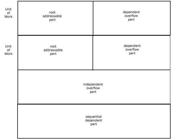
Figure 2-17: DEDB area structure.
A Unit of Work (UOW) is further divided into the root addressable part and the dependent overflow parts. Record storage in the root-addressable and dependent overflow parts of a UOW closely resembles record storage in an HDAM database. The root and as many segments as possible are stored in the root addressable part, and additional segment occurrences are stored in the dependent overflow part.
If the size of a record exceeds the space available in the root-addressable and dependent overflow parts, segments will be added in the independent overflow part.
Because a UOW is totally independent of other UOWs, you can process a UOW independently of the rest of the DEDB. The ability to continue processing the remainder of an area while reorganizing a single UOW significantly increases the data availability of a DEDB database.
Figure 2-18 shows the configuration of a VSAM CI within a UOW.
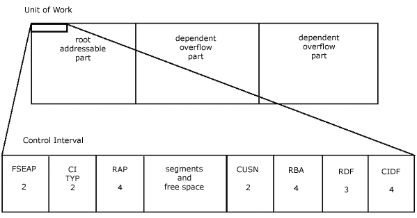
Figure 2-18: Configuration of a control interval within a unit of work.
| FSEAP | This field gives the offset in bytes to the first free space element (FSE). If the CI is in the sequential dependent part, these two bytes are not used. |
| CI TYP |
This describes the type of CI. 1 base section 2 overflow section 3 independent overflow part 4 sequential dependent part |
| RAP | This contains the root anchor point if the CI is in the root addressable part of the area. Only one RAP exists per CI. Other roots randomized to this CI will be chained off of this RAP in ascending key sequence. |
| CUSN | CI update sequence number. This number is increased by one with each update of the CI. |
| RBA | Relative byte address of this CI. |
| RDF | Record definition field. This contains information on the records stored in the CI, their length, and whether they are fixed length or variable length. |
| CIDF | CI definition field. This field contains information on the control interval itself. It keeps track of the amount of free space available and where the free space is located, relative to the beginning of the CI. Control intervals will have only one CIDF but may have a variable number of RDFs, depending on whether the CI contains fixed-length or variable-length records or a combination of the two. |
Sequential Dependent (SDEP)
DEDBs employ a special segment type called sequential dependent (SDEP). Sequential dependents are designed for very fast insertion of segments or to accommodate a very high volume of inserts. They must be located in the hierarchy as the first child of the root segment, and they occupy their own space in an area. Although SDEPs perform well for insert operations, they are not as efficient at online retrieval. For this reason, SDEP segments are often retrieved sequentially by using the SDEP Scan utility and are processed further by offline jobs.
The sequential dependent part of the area is used solely for the storage of sequential dependent segments. These segments are added in chronological order, regardless of which root they belong to. They are chained back to the root in reverse order by pointers.
The purely sequential nature of SDEPs allows rapid insertion of new SDEP segment occurrences. SDEPs can only be written and read sequentially, and REPLACE and DELETE calls are not allowed. When the sequential dependent part is full, new segments must be added at its beginning. For this reason, the SDEP area must be purged periodically. The SDEP Scan utility can be used to extract SDEP segments from an area while online processing continues. The Sequential Dependent Delete utility allows you to delete some or all of the SDEPs while online processing continues.
SDEPs typically are used for temporary data. They are often used for recording processing events that occur against a record during a particular time period. A bank, for example, might record the activity of each customer account during the day in SDEPs that are read and processed later offline.
Other DEDB segment types are direct dependent segments (DDEPs). They can be stored and retrieved hierarchically and support ISRT, GET, DLET, and REPL calls. IMS attempts to store DEDB DDEPs in the same CI as the root segment. If space is not available in the root CI, IMS will search the dependent overflow and then the independent overflow parts. You can define DDEP segments with or without a unique sequence field. DDEPs are chained together by a PCF pointer in the parent for each dependent segment type and a PTF pointer in each dependent segment. Figure 2-19 illustrates the format of a DEDB record.
Figure 2-19: DEDB record format.
Root and direct dependent segments can be stored in the root addressable part of a UOW or the dependent overflow part, if the root addressable part is full. The independent overflow part consists of empty CIs that are not initially designated for use by a specific UOW. Any UOW can use any CI in the independent overflow part. When a UOW begins using a CI in the independent overflow part, however, the CI can be used only by that UOW. The sequential dependent part of an area stores SDEPs in the order in which they are loaded, without regard to the root segment or the UOW that contains the root.
Although a DEDB can be compared in structure to HDAM, there are a number of important differences between the two. DEDBs have the following restrictions:
- do not support secondary indexes
- do not support logical relationships
- allow unique key field or no key field for a segment; do not support non-unique key fields
- do not support batch processing
DEDBs are supported by DBRC and standard IMS logging, image copy, and recovery procedures. DEDB areas are accessed by using VSAM improved control interval processing (ICIP).
Randomizing Module
IMS uses a randomizing module to determine the location of root segments.
The randomizing module addresses records by:
- ascending area number
- ascending UOW
- ascending key in each anchor point chain
Multiple Area Data Sets
IMS allows a DEDB area to be replicated (copied) up to seven times, thus creating multiple area data sets (MADS). You can do this using the DEDB Area Data Set Create utility, which lets you make multiple copies of an area without stopping processing. The copies you create must have the same CI sizes and spaces, but they can reside on separate devices. Although IMS allows seven copies plus the original, for a total of eight iterations of the same area, most IS shops use no more than two or sometimes three copies, to avoid excessive use of DASD space.
As changes are made to data within one area of a MADS, IMS automatically updates all copies to ensure the integrity of the data throughout the MADS. If one area of the MADS fails, processing can continue with another copy of the area.
If an error occurs during processing of an area, IMS prevents application programs from accessing the CI in error by creating an error queue element (EQE) for the error CI. IMS uses the EQE to isolate the CI in error while allowing applications to access the remainder of the area. When IMS detects errors on four different CIs within an area, or when an area has experienced more than 10 write errors, IMS stops the area. Because other copies of the area are available, IMS can continue processing by using the same CI in one of the copies.
MSDBs
Main storage databases (MSDBs) are so named because the entire database is loaded into main storage when processing begins. This makes them extremely fast, because database segments do not have to be retrieved from DASD. Most IS shops reserve MSDBs for a site's most frequently accessed data, particularly data that requires a high transaction rate. The fact that MSDBs require memory storage limits their size.
In addition to being executed in main storage, MSDBs gain speed from a number of other processing conventions. Update calls are not executed immediately; rather, updates are held for simultaneous execution when a synchronization point is reached. Also, MSDBs support field calls, a feature that allows MSDB segments to be updated at the field level while permitting other programs access to other fields within the segment at the same time. Finally, MSDBs are made up of fixed-length root segments only. Because there are no dependent segments, segment searches are simplified. There are two general types of MSDBs: terminal-related and nonterminal-related.
Terminal-Related MSDBs
With terminal-related MSDBs, each segment occurrence is associated with, or owned, by a specific logical terminal. Only the logical terminal that owns a segment is allowed to update the segment, but all logical terminals are allowed to retrieve all segments. The name of the logical terminal that owns the segment is used as the key of the segment. The key of a terminal-related segment does not actually reside in the segment. Terminal-related MSDBs are used when segments contain data that can be associated with a specific user or terminal.
Terminal-related MSDBs are divided into two types:
- terminal-related fixed
- terminal-related dynamic
Terminal-related fixed MSDBs do not allow segments to be inserted or deleted. They can be retrieved and updated only. Terminal-related dynamic MSDBs allow segments to be inserted or deleted.
Nonterminal-Related MSDBs
With nonterminal-related MSDBs, segments are not owned by any terminals. An application program can read and update any segment; however, insert or delete calls are not allowed.
There are two types of nonterminal-related MSDBs
- nonterminal-related with terminal keys
- nonterminal-related without terminal keys
With nonterminal-related with terminal keys, the name of a logical terminal or a field in the segment is used as the key of the segment. As with terminal-related fixed segments, if the terminal name is used as the key, it does not reside in the segment. For nonterminal-related without terminal keys, terminal names are not used as keys; a data value is used as key. The key can be any part or all of the field, but it must reside in the sequence field of the segment.
Nonterminal-related MSDBs are typically used when a large number of users need to update data frequently, such as users at point-of-purchase terminals.
Virtual Storage Option
The Fast Path Virtual Storage Option (VSO) for DEDBs allows you to achieve performance improvements similar to those of MSDBs by loading one or more DEDB areas into virtual storage. You do this by defining the DEDBs as VSO areas. VSO areas must be registered with DBRC and do not allow block-level sharing while the area is in virtual storage. Otherwise, they are the same as non-VSO DEDB areas.
The Role of Secondary Indexes
A secondary index lets you process a segment type in a sequence other than that defined by the segment’s key. You can base a secondary index on any segment in the database, including the root, and you can create more than one secondary index on any segment. In fact, you can use up to 32 secondary indexes for a segment type and a total of 1,000 secondary indexes for a single database. A secondary index allows you to have an index based on any field in the database. This section describes how secondary indexes can be used to solve access needs in the sample College databases.
Secondary indexes can be used with HD databases and with HISAM. A secondary index uses VSAM as its access method. A secondary index is a self-contained database, with its own DBD, containing segments that point to a segment in the primary database. Each secondary index’s DBD contains parameters that connect it to the primary database.
Let’s look again at the College database created in Chapter 1, “IMS Concepts.” It is shown again in Figure 2-20.
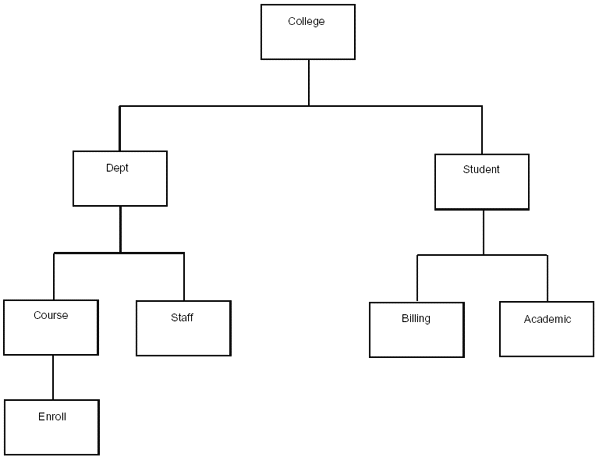
Figure 2-20: College database.
As part of our database, we decided to list the students enrolled in a specific course. We handled this requirement by creating the Enroll segment as a dependent of Course. Suppose that the Enroll segment has the data fields shown in Figure 2-21.
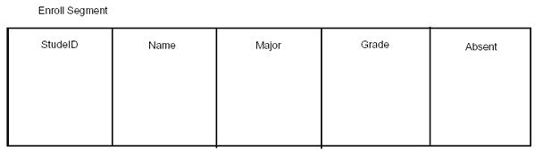
Figure 2-21: Data fields of the enroll segment.
If we retrieve the occurrences of the Enroll segment in key sequence order, we will have a list based on student ID number. But suppose we want the information in this segment in an alphabetical list based on the student’s names. To create this list using the StudeID field would be difficult. If we create a secondary index based on the Name field, we can generate our listing easily by processing sequentially on the new Name key field.
You can also use the secondary index to access segments individually. You do this by referring to them specifically by the secondary index name (remember, the secondary index is a database) in the segment search argument you write.
Finally, you can treat the secondary index as a database and use the information stored in it. Using our StudeID secondary index, we can retrieve just the contents of the field to which it points, giving us an alphabetical list of student names.
When you want an application to perform processing by using a secondary index, you must code the PROCSEQ parameter in the application program PCB. This identifies the index database to the application program. If you want the application program to use the database’s regular processing sequence, do not include the PROCSEQ parameter. You can have the application program use the regular processing sequence and the secondary index by including two PCBs in the application program’s PSB. One PCB contains the PROCSEQ parameter and one does not.
Secondary Index Segments
The segments used in setting up a secondary index are referred to as the source, target, and pointer segments, depending on their function within the index structure. When you set up a secondary index, you must define to IMS which segments will act in which capacity.
Source Segment
The source segment in the primary database contains the field that is being used as the pointer segment’s key field. The secondary index will be sequenced on this field. In Figure 2-20, Enroll was the source segment.
Target Segment
The target segment in the primary database is the segment to which the index points. It is the segment that is retrieved when the secondary index is used. In many cases, but not always, the target segment is the same as the source segment. In Figure 2-20, the Enroll segment is the target segment.
Pointer Segment
The pointer segment is the only type of segment that is stored in the secondary index database. (Target and source segments are in the primary database.)
Index Pointer Segment Layout
Figure 2-22 shows the index segment’s configuration.
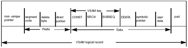
Figure 2-22: Index pointer segment layout.
The layout of the index pointer segment is as follows:
| Non-Unique Pointer | Optional. This 4-byte field is present only when the pointer segment contains non-unique keys. It is used to chain together the KSDS and ESDS logical records with the same key value. It is not part of the segment prefix. It is not reflected in the prefix length of the generated DBD. |
| Segment Code | Optional. This 1-byte field appears only if DOS COMPAT was specified in the index DBD. The prefix length in the generated DBD always assumes this field is present, even though it may not be present. |
| Delete Byte | Required. This 1-byte field is always present. At load time it contains X'00'. |
| Direct Pointer | Optional. This 4-byte field is present if the secondary index is pointing to an HD-type database and direct pointing was selected. It contains the 4-byte RBA of the target segment. |
| CONST | Optional. This 1-byte field contains a user-specified constant. It is required for a shared secondary index. If present, it forms part of the VSAM key. SRCH Required. It consists of one to five fields copied from the index source segment. This field is the VSAM key. This is the data used to qualify a call when accessing the target segment by using the secondary index. |
| SUBSEQ | Optional. It consists of one to five fields copied from the index source segment. If present, it is concatenated with the search (SRCH) data to produce a unique VSAM key. |
| DDATA | Optional. It consists of one to five fields copied from the index source segment. It is available only when processing the secondary index as a separate database. |
| Symbolic Pointer | Required if the primary database is HISAM. Optional for HD-type primary databases. It is mutually exclusive with direct pointers. If present, it contains the concatenated key of the target segment, which must be unique. The symbolic pointer may be a separate field or may be imbedded in the SUBSEQ or DDATA fields. |
| User Data | Optional. It is inserted and maintained by the application program after the secondary index has been created. There is no operand in the XDFLD macro to define this area. It is the residual space left in the logical record after space for all requested fields is satisfied. |
| Pad | Optional. This 1-byte field is not part of the segment data and is present only if it is necessary to make the logical record length an even integer to satisfy the VSAM requirement. |
Secondary Index Implementation
Secondary indexes can accommodate non-unique keys. You can create a secondary index based on a field that will not always be unique. In our previous example, we discussed creating a secondary index based on student name. It is quite possible for two students to have the same name, particularly if you are indexing on the last name only. You would certainly have non-unique keys if you created a secondary index based on the Major field. When this occurs, IMS creates a SYNRBA field in the pointer segment of the secondary index. The SYNRBA field contains a pointer that points to duplicate key segments. Duplicated key segments are stored in a VSAM ESDS and are chained together by pointers of this type. This section discusses secondary index implementation using non-unique or unique keys.
Non-Unique Keys
To implement a secondary index with non-unique VSAM keys, two VSAM data sets are required. The first (or only) occurrence of a non-unique key is placed in a KSDS. Subsequent occurrences of that key are placed in an ESDS. Logical records containing multiple occurrences of the same key are chained together. IMS implements this chain by appending a 4-byte RBA pointer to the front of each record.
Figure 2-23 shows the implementation of a secondary index with non-unique
keys.
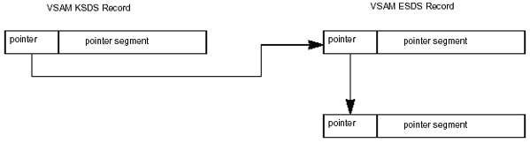
Figure 2-23: SecondaryiIndex implementation with non-unique keys.
Unique Keys
When unique VSAM keys are present, no ESDS is required and no 4-byte pointer is appended to the front of each logical record. Figure 2-24 shows the implementation of a secondary index with unique keys.
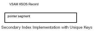
Figure 2-24: Secondary index implementation with unique keys.
Manuals have been written on the use of secondary indexes, and a complete discussion of the subject is beyond the scope of this book. They are an extremely powerful tool for use with IMS databases, however, and should be a part of every IMS DBA's data management strategy.
The Role of Logical Relationships
IMS provides the ability to create special types of segments that access data in other segments through the use of pointers. You can create a segment type that contains no data but points to a segment in the same or another database to access the data stored there. Because the segment is not actually a physical child of the segment to which it points, it is called a logical child. And because the path established between the logical child and the segment to which it points is not a physical relationship, it is called a logical relationship.
The ability to create logical relationships among database segments is a powerful feature of IMS. It lets you avoid the need to store redundant data, and it lets you create new database hierarchies without creating new databases. By establishing a logical relationship, you can create a hierarchy that does not actually exist in storage but can be processed as if it does. You can relate segments that exist in separate hierarchies within the same database or in separate databases.
Note: Logical relationships cannot be used with Fast Path DEDB or MSDB databases.
To illustrate the concept of logical relationships, let's look again at the example College database. Suppose we decide that, as part of the College database, we want a segment under Dept that lists the classrooms being used for each course. We could create a new segment, Rooms, as a dependent. But suppose we discover that the physical descriptions we need are already contained in a segment of another database. The data we need is included in the Units segment of the Buildings database. It would be redundant to repeat the same data in our College database. By doing so, we would be vulnerable to the problems associated with duplicate data:
- It requires additional maintenance to keep the duplicate sets of data up to date and synchronized.
- It requires extra DASD to store the duplicate data. We can achieve the effect of a new Rooms segment in the College database by creating a logical data structure that ties the College and Building databases together. To do this, we create a logical DBD that defines the structure we want. In the College database, where we want our Rooms segment, we create what is called a logical child segment. It points to the Units segment in the Buildings database. The Units segment, where the data is physically stored, is referred to as the logical parent. In our logical child segment, Rooms, we simply store pointers that point to the appropriate occurrences of the Units segment, the logical parent.
The logical relationship we have just established gives us the logical structure shown in Figure 2-25.
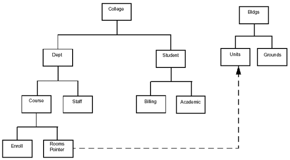
Figure 2-25: Logical structure based on college and buildings databases.
Figure 2-25 is an example of a unidirectional logical relationship. It is called unidirectional because we can go in only one direction, from the College database to the Units segment. You can use the Rooms segment of the College database to find information on classroom space available for courses, but you could not use any segment of the Buildings database to find information on what courses are being taught in specific rooms. You can, however, create logical relationships that will allow you to access data in both directions. In addition to unidirectional relationships, you can create two types of bidirectional relationships-physically paired and virtually paired.
Physical Pairing
Suppose that we want to be able to access data in the College database as if the data were in a segment of the Buildings database. When we access the Units segment of the Buildings database, we want to know which courses will be taught in each room. We can do this by storing the Rooms logical child segment in the Buildings database and pointing to the Course segment in the College database. As a room is assigned to a course, the Rooms logical child will be updated in both databases. We will have a bidirectional path that lets us determine what room a course will be taught in and what courses will be taught in any room. The Rooms segment is physically stored in both databases and the segments are said to be physically paired. IMS automatically updates both logical child segments when a logical parent segment occurrence is added.
Virtual Pairing
In the discussion of physical pairing, we discovered how to link to databases bidirectionally by using two logical child segments, one in each database. By using virtual pairing, we can do the same thing without creating a logical child in the Buildings database. Instead, we can add another pointer in the Rooms logical child in the College database to give us a two-way path between the two databases. This gives us the effect of two logical child segments, although we only have one. The logical child that is stored in the College database is called the real logical child. The logical child that is created by the second pointer in the real logical child is called the virtual logical child. The relationship we have created between the two database segments is called bidirectional virtual pairing.
Intersection Data
When two segments are logically related, it is possible to create data that is relevant only to the relationship. For example, in our College database, the number of seats available in the room where a course will be taught is a unique combination of the course and the room assigned for it. This information could be useful in determining if the enrollment for a course has exceeded the number of seats available. This type of data is called intersection data. It is meaningful only in the context of the two logically related segments. Intersection data is stored in the logical child segment. There are two types of intersection data:
- fixed intersection data (FID)
- variable intersection data (VID)
Fixed Intersection Data
Fixed intersection data is any data stored in the logical child. When you are using direct pointing, FID is the only data in the logical child segment. In symbolic pointing, the FID is stored in the data portion of the segment after the LPCK.
Variable Intersection Data
Variable intersection data is used when you have several occurrences of intersection data for the same logical relationship. It is stored as a dependent of the logical child, and there can be as many occurrences per logical child as needed.
Use of Pointers in Logical Relationships
Pointers used in logical relationships fall into two categories-direct and symbolic. It is possible to implement logical relationships using both types. The major differences are that a direct pointer is a true pointer. With a direct pointer, the logical child segment contains the address of the logical parent segment to which it points. With a symbolic pointer, the logical child segment contains the key of the logical parent segment to which it points. Four types of pointers can be specified in logical relationships:
- logical parent (LP)
- logical child (LC)
- logical twin (LT)
- physical parent (PP)
Logical Parent Pointers
LP pointers point from the logical child to the logical parent. When pointing into HDAM and HIDAM databases, an LP pointer can be a direct pointer or a symbolic pointer. It must be a symbolic pointer if pointing into a HISAM database; however, direct LP pointers can exist in a HISAM database as long as they are not pointing into a HISAM database. Because pointers are not required between segments in a HISAM database, the only time direct pointers are used in them is to maintain a logical relationship with an HD database.
A symbolic LP pointer consists of the logical parent's concatenated key (LPCK). A symbolic LP pointer can point into a HISAM database or HD database. It is stored in the first part of the logical child segment.
In HISAM or HIDAM databases, IMS uses symbolic pointers to access the database's index and (from there) to locate the logical parent segment. In HDAM, the randomizing module changes the symbolic pointer into a block and RAP address to find the logical parent.
Logical Child Pointers
Logical child pointers are used only for logical relationships that use virtual pairing. With virtual pairing, only one logical child exists on DASD, and it contains a pointer to a logical parent. The logical parent points to the logical child segment. Two types of logical child pointers can be used:
- logical child first (LCF)
- a combination of LCF and logical child last (LCL) pointers
Because LCF and LCL pointers are direct pointers, the segment they are pointing to must be in an HD database. The logical parent (the segment pointing to the logical child) must be in a HISAM or HD database. If the parent is in a HISAM database, the logical child must use a symbolic pointer to point to the parent.
Logical Twin Pointer
Like logical child pointers, logical twin pointers are used only for logical relationships that use virtual pairing. Logical twins are multiple occurrences of logical child segments that point to the same occurrence of a logical parent segment. Two types of logical twin pointers can be used:
- logical twin forward (LTF)
- a combination of LTF and logical twin backward (LTB) pointers LTF pointers point from a logical twin to the logical twin stored after it. LTB pointers, used only with LTF pointers, point from a logical twin to the logical twin stored before it. Logical twin pointers function similarly to the physical twin pointers described in "Physical Twin Forward and Backward Pointers."
LTF and LTB pointers are direct pointers, containing the 4-byte address of the segment to which they point, and can exist only in HD databases.
Physical Parent Pointer
Physical parent (PP) pointers point from a segment to its physical parent. IMS generates PP pointers automatically for HD databases involved in logical relationships. They are put in the prefix of all logical child and logical parent segments and in the prefix of all segments on which a logical child or logical parent is dependent in its physical database. Having a PP pointer in each segment in the chain from logical segment to physical parent creates a path back to the root segment on which the segment is dependent. This allows access to any of the segments in the chain in forward or backward order.
As with direct pointers, PP pointers contain the 4-byte address of the segment to which they point.
Last modified 2005-05-19 11:26 AM